顯示具有 ArcGIS 標籤的文章。 顯示所有文章

2008年10月27日

Make a contour by ArcGIS

Before using ArcGIS, please make sure the tool”Spatial Analyst” has chosen.
(if not, go to check “tool”-->”customize”-->”toolbars”-->”spatial analyst”

1.the same as ArcView, Be sure your data is numeral.
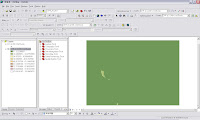
2.Open ArcMap,
“tools”-->”add XY data”, then the interface will look like this


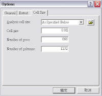
3.Definition the range of analysis
Spatial Analyst-->Options-->Cell size-->AS specified below(you can choose any size you want , for this example, it’s “0.01”
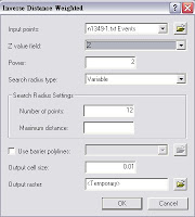


4.Point-->contour
Spatial Analyst-->Interpolate to RasteràInverse Distance Weighted.
In Z value field, choose the data you want to draw, then clip OK


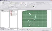
5.Final, the appearance will like that.


2008年9月20日

如何截取你想要的圖。

在研究上,碰到一個案例,就是有一張圖外面是台北縣,裏面是台北市。但是我只想要台北市的圖就好。那該怎麼做呢?
在arccatalog中,創造一個shp檔。記得在創造的時候,要選擇"面"(有點、線、面可以選).之後在叫出gismap,開啟剛建立的shp檔跟台北縣市的圖層。然後按編輯,選擇編輯剛建立的shp檔,繪製一個跟台北市大小差不多的長方形。之後儲存編輯,並關掉編輯。在toolbox,選擇intersect,把剛編輯的shp檔與台北縣市圖層作intersect,intersect之後的圖,就是你想要的單純的台北市的圖層了!!!!!

關於坐標轉換與從gis匯入坐標點的方法。

第一個:坐標的轉換。從經緯度轉換到TM2。先把分跟秒轉換成度的單位。例如:分要乘於1/60, 秒要乘於1/3600。加上度。完全變度後,利用transform的軟體轉換成TM2。值的一提的是,東經是x軸,北緯是y軸喔。不要搞混喔。我記得有一次就搞混,填了相反的值,轉換出來,我當場傻眼,以為這轉換的軟体,是不是程式寫錯了。要切記!要切記!
第二個:匯入坐標點的方法。先在excel中,第一列先打X,Y。之後打上你要的坐標點。儲存成其它格式,儲成CSV檔。之後就可以在GIS中,讀的到了。另外也有一個方法,就是在記事本中,第一列打X,Y,接下來,在下面打你要輸入的座標。記得要座標與座標之間要用逗號(,)喔。打好之後,在GIS就會讀的到了。也許你會問,那空白隔的開,GIS會讀的到嗎?答案是:讀不到的。

2008年9月3日

ArcGIS 9.2 Installation

台大校園版ArcGIS 9.2安裝步驟 (參考台大地理系提供之安裝步驟)

學校版的ArcGIS 9.2,可至ftp://140.112.64.249,用帳號esri,密碼esri123登入下載。
下載後,用內附的Alcohol 120%來燒成DVD光碟片。

ArcGIS是ESRI公司GIS系列產品的統稱,一般最常用的產品是 ArcMap和ArcCatalog。
安裝之大致步驟
  1. 置入光碟片
  2. 選ArcGIS Desktop
  3. 選Install ArcGIS Desktop
  4. 遇到問License Manager時,輸入140.112.64.90
  5. 建議選擇?完整安裝?(complete installation)

若有一些錯誤,不要管它,直到安裝完,即可使用了。

詳細的安裝步驟可以參考
http://www.bp.ntu.edu.tw/WebUsers/ftlin/course/gis/台大校園ArcGIS 詳細安裝程序.doc
實際的步驟可能隨著版本而略有不同,但基本上,程序是一樣的

啟動ArcMap
  1. 於 開始/所有程式/ArcGIS下,點選ArcMap
  2. 可以先選a new empty map,按 OK
  3. Tools/ Extensions/
  4. 選擇 3D Analyst, Geostatistical Analyst, network analyst, spatial analyst,…等常用的空間分析功能

2008年8月29日

AGGREGATE IN ARCGIS

以下要介紹有關於(1.)將excel檔存成dbf檔的小技巧

(2.)用ARCGIS作aggregation


  1. excel檔存成dbf檔的小技巧

據說以前的excel可以直接存成dbf檔,可是現在excel不支援了!

所以運用microsoft office access資料庫來轉換檔案格式

Step. 用access來開啟excel檔案→檔案按右鍵匯出→選取dbase檔案→完成


  1. 用ARCGIS作aggregation

    前言:因為我手邊登革熱資料的鄉鎮行政去劃分跟台灣鄉鎮地圖不一樣,一

    個將中區跟西區分開,另一個則是合稱中西區,要將中區、西區併在

    一起,需要運用aggregate作結合。


    Step1.將這兩區的編碼改成相同的


Step2.儲存,並將excel檔轉成dbf檔

Step3.開啟ARCGIS→運用help的功能在索引上打aggregate→選擇coverage

data →dissolve(coverage)


Step4.按下related topics→在點選dissolve的選項


Step5.按open tool按鍵,會出現dissolve視窗→input data→勾選需要aggregate的項目,其餘項目再做運算


Step6.在data table上按options→add field→輸入名稱


Step7.在標題上按右鍵→calculate geometry→yes→完成所有資料整合與內容恢復


2008年6月3日

設定台灣地理坐標的方法

我定義系統坐標的方法如下:
First of all →starting arcCatalog→瀏覽這三張圖層 →在圖層上直接點兩下或是按滑鼠右鍵,選擇properties →在選XY coordinate system→如果此圖層沒有座標系統的話,details:是空白的→由於arcgis並沒有內鍵的台灣的TM2度分帶的投影座標系統格式,所以我必須新增→選擇new→projected→name:TM67(or TM97)→projection’s name:Transverse_Mercator→false_Easting:250000,false_Northing:0,Central_Meridian:121,Scale_Factor:0.9999,Latitude_Of_Origin:0→Linear Unit name:Meter→按一下select→Geographic Coordinate System→Asia→Taiwan1967(或taiwan1997, 若想要兩個都建立的話,重複上述的steps)→套用→確定→完成了新增座標系統之後,不要忘了將你的所新增的座標系統,儲存起來→Save as →存在projected coordinate systems裏→以後要用時就方便了。

如何截取一個圖層的中你想要的部份及如何設定你想要的圖層中的坐標單位。

1、這問題非常的簡單,在你要截取的圖層,按右鍵>>open attribute table>>選擇你的要資料後>>再回圖層,也是按右鍵>>data>>export data 。這樣就有截取你想要的圖層了。
2、view→data frame properities→general。就會看到units。有兩個-map跟display都選。

設定gis的地理投影座標系統。

我定義系統坐標的方法如下:
First of all →starting arcCatalog→瀏覽這三張圖層 →在圖層上直接點兩下或是按滑鼠右鍵,選擇properties →在選XY coordinate system→如果此圖層沒有座標系統的話,details:是空白的→由於arcgis並沒有內鍵的台灣的TM2度分帶的投影座標系統格式,所以我必須新增→選擇new→projected→name:TM67(or TM97)→projection’s name:Transverse_Mercator→false_Easting:250000,false_Northing:0,Central_Meridian:121,Scale_Factor:0.9999,Latitude_Of_Origin:0→Linear Unit name:Meter→按一下select→Geographic Coordinate System→Asia→Taiwan1967(或taiwan1997, 若想要兩個都建立的話,重複上述的steps)→套用→確定→完成了新增座標系統之後,不要忘了將你的所新增的座標系統,儲存起來→Save as →存在projected coordinate systems裏→以後要用時就方便了。

2008年5月30日

Projection transformation

It has been confused me for a while. How to define or transform the projection of a shapefile in ArcGIS such that it can align with other maps with different coordinate system. Here is the steps in ArcGIS 9.X.
  1. Figure out the original projection of your map even though it has not been defined before, namely it does not have any projection file (*.prj) along with other files for shapefile.
  2. Two coordinate system can be defined in a shapefile, one is geographical coordinate system which is essentially for longitude and latitude; the other one is projected coordinate system which is for the planar coordinate (two-dimension)
  3. To define a coordinate system to a shapefile, Go to ArcToolbox -> Data Management Tools -> Projections and transformations -> Define projection, and then a window will popup for us to select the shapefile (feature class) to define and the coordinate system
  4. To change a coordinate system of a shapefile in order to align with other shapefile,
    1. Determine the coordinate system to which we would like to transform
    2. Go to ArcToolbox -> Data Management Tools -> Projections and transformations ->Feature -> Project
    3. Specify the shapefile to transform (feature class), the name for the new shapefile with new coordinate system (projection), and the new coordinate system in the popup window
    4. OK
  5. The new shapefile will automatically be added into the current project
  6. Note that the table of the new shapefile is exactly the same as the original shapefile. The new geometry values upon the new coordinate system can be generated by adding new field in the Table and do the Geometry calculation.

To adjust the position of maps in ArcGIS

Here I encounter an interesting problem that two Taiwan shapefile with two different administrative units can not completely overlay to each other (shown in the first figure below). It confused me a lot and made me think that the projection definition can be an issue for these maps. Some solution for the change of projection system in ArcGIS is discussed in this document. The projection definition indeed has some issue in Taiwan area where several definitions exist concurrently and are inconsistent. For the detail information about the projection issue in Taiwan.
  1. Introduction to projection system and definition of two-degree transverse Mercator (二度分帶)
  2. The webpage for the description the three common Transverse Mercator system TWD67 (Taiwan Datum 67), TWD97 (Taiwan Datum 97), WGS84 (World Geodetic system 84)
  3. A very informative educational website
  4. Projection system transformation
However, in fact, the solution of the displacement of these two shapefiles in ArcGIS does not have anything to do with the coordinate systems, according to the experience drawn from the trials by myself and my student. Here is the solution to adjust the map proposed by Chi-Shih
  1. 開啟arcmap選擇a new empty map
  2. 看到一個黃色+號圖形,把這三張圖讀出
  3. toolseditor bars→會出現編輯的工具列
  4. editorstart editing→就可以開始編輯
  5. 先打勾里村跟縣市(或鄉鎮)作對比
  6. 看完對比之後,只那村里勾選→用滑鼠把外島那一部份框起來,移至最左邊,不要擋到其它那兩張圖外島的位置就行了
  7. 然後勾選其它兩張任一張圖,做對比→一一的移動到適當的位置
  8. 完成了之後,到editorstop editing→它會問要不要存檔→ok→即完成


Extract points from polyline in ArcGIS

Here is a visual basic macro for ArcGIS to generate points on the polylines. How to use these codes. Few steps are discussed below:
  1. Add the polyline shapefile in your ArcMap project.
  2. Create a point shapefile in ArcCatalog by right-click a specific folder and select New to create a new point shapefile in which the to-be-generated points will be saved.
  3. In ArcMap, Go to Tool > Macro > Visual Basic Editor > Project > ArcMap Objects > ThisDocument
  4. Copy the VB script attached below and paste into ThisDocument
  5. Highlight the polyline shapefile to be extracted
  6. Click the "Run Sub" button to execute the script
  7. Done !!
----------------------------------------------------
Public Sub CreatePointsAlongCurve()
'Creates points at a set distance along any feature implementing ICurve
'
'Justin Johnson
'January 23, 2004
'justin.johnson@geog.utah.edu
'
'Obtains selected features from currently-selected Layer
'Stores new points in point theme at top of TOC

Dim pMxDoc As IMxDocument
Dim pMap As IMap
Dim pInGeometry As IGeometry
Dim pInLayer As ILayer
Dim pInFLayer As IFeatureLayer
Dim pOutFLayer As IFeatureLayer
Dim pInFCursor As IFeatureCursor
Dim pOutFCursor As IFeatureCursor
Dim pOutFBuffer As IFeatureBuffer
Dim pInFClass As IFeatureClass
Dim pOutFClass As IFeatureClass
Dim pSelSet As ISelectionSet
Dim pFSelection As IFeatureSelection
Dim pInFeature As IFeature
Dim pCurve As ICurve
Dim pPointCollection As IPointCollection
Dim pConstructMultipoint As IConstructMultipoint

Set pMxDoc = ThisDocument
Set pMap = pMxDoc.FocusMap
Set pInLayer = pMxDoc.SelectedLayer

If pInLayer Is Nothing Then 'Check if no input layer is selected
MsgBox "Select a feature layer in the TOC", vbCritical, "Incompatible input layer"
Exit Sub
End If

If TypeOf pInLayer Is IFeatureLayer Then 'check if selected layer is a feature layer
Set pInFLayer = pMxDoc.SelectedLayer 'set selected layer as input feature layer
Else
MsgBox "Select a feature layer in the TOC", vbCritical, "Incompatible input layer"
Exit Sub
End If

Set pOutFLayer = pMap.Layer(0) ' set top layer in TOC as output feature layer
Set pInFClass = pInFLayer.FeatureClass
Set pOutFClass = pOutFLayer.FeatureClass

If Not pOutFClass.ShapeType = esriGeometryPoint Then 'check if output layer is Point type
MsgBox "Geometry type of output layer is not Point", vbCritical, "Incompatible Output Layer"
Exit Sub
End If

'Get selected features, if any
Set pFSelection = pInFLayer
Set pSelSet = pFSelection.SelectionSet

'Prompt user for distance between points
Dim pPointDist As Double
pPointDist = InputBox("Distance between points: ", "Point Spacing in Map Units")

'Create an Insert cursor on output feature class
Set pOutFBuffer = pOutFClass.CreateFeatureBuffer
Set pOutFCursor = pOutFClass.Insert(True)

If pSelSet.Count <> 0 Then
'use selected features from input feature class
pFSelection.SelectionSet.Search Nothing, True, pInFCursor
Else
'use all features if none are selected
Set pInFCursor = pInFClass.Search(Nothing, True)
End If

Dim k As Long 'count the number of points created
k = 0

Set pInFeature = pInFCursor.NextFeature

Do While Not pInFeature Is Nothing

Set pInGeometry = pInFeature.Shape
Set pCurve = pInGeometry
Set pConstructMultipoint = New Multipoint

pConstructMultipoint.ConstructDivideLength pCurve, pPointDist

Set pPointCollection = pConstructMultipoint

Dim i As Long
For i = 0 To pPointCollection.PointCount - 1

Set pOutFBuffer.Shape = pPointCollection.Point(i) 'store the new geometry
pOutFCursor.InsertFeature pOutFBuffer
k = k + 1

Next i

Set pInFeature = pInFCursor.NextFeature

Loop

pMxDoc.ActiveView.Refresh
MsgBox k & " points created in " & pOutFLayer.Name, vbInformation, "Complete"

End Sub

Load DEM into ArcGIS

I download the DEM (Digital Elevation Model) files from Geocommunity to do the exercise of Archydro model to analysis DEM file for the collection of geographical information. Geocommunity is the free port providing the free GIS files from all over the world. Its format of DEM files is SDTS (Spatial Data Transfer Standard). In order to transfrom the SDTS file into the suitable format for ArcGIS 9.2 use, we should add the new extension by going to ArcCatalog->Tools-> Customize-> Arcview 8x tools.
The transformation of SDTS file to Grid file for the DEM analysis, it follows the steps
  1. Open ArcToolbox
  2. Under Conversion Tools > Import to Raster, choose 'SDTS Raster to Grid'
  3. In the Input Prefix box, navigate to the folder with the ****.ddf files, and choose the 4 digit input file (ex:1158). Note that the path for the .ddf files may not contain any spaces.
  4. Choose the Z-value field name for the Record No. box, i.e. "ELEVATION".
  5. Select an output folder and name the Grid.
  6. Keep Convert Values and Use Data Dictionary checked.
  7. Hit OK.
  8. You may then add this DEM Grid to ArcInfo Desktop or ArcView 3.x
For more comprehensive information, we can go to the website.

How to merge polygon in ArcGIS?

Case 1: Automatically merge all small polygons into a big one with respect to a specified attribute.
We can refer to the dissolve function in ArcToolbox.

Case 2: If the two specific polygons are expected to merge, follow the steps as follows
a. Select Editor > Start Editing.
b. Toggle the original polygon layer invisible.
c. Select the polygon features from the new polygon layer to be merged.
d. Select Editor > Merge.
e. The Merge dialog lists the polygon features to be merged. Click OK to merge the polygons features.
f. Select Editor > Stop Editing and click Yes to save the edits.

For more info, we can refer to the ESRI website

One note:
The dissolve function in ArcGIS 9.2 is not as capable as it was in Arcview 3.2. The dissolve function can experience memory limitation difficulty once the shapefile is too big. The workaround for the polygon dissolving is the usage of Arcview 3.2 geoprocessing wizard.